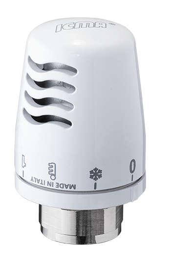
- Termostatic head
- Valves with thermostatic option for double pipe
- Double settings thermostatic valves for double pipe systems
- Thermostatic kit and thermostatic valves for double pipe systems
- Manual valves and lockshields for double pipe systems
- Four-way valves with thermostatic option for single pipe and double pipe systems
- Single pipe manual valves
- Fittings for copper, pex-al-pex, pex pipe, radiator eccentrics, elbow fittings, rosette
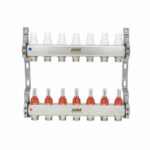
- Single/double pipe distributors for panel with built-in thermostatic group
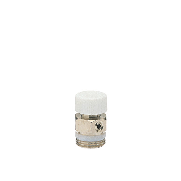
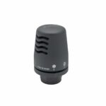
- Radiator air vents
- Valves and lockshields for design radiators
- Chromed thermostatic head and rosettes with pipe cover


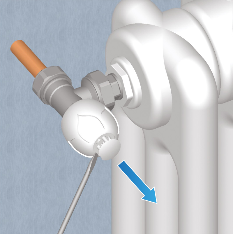
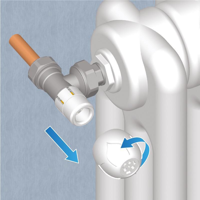
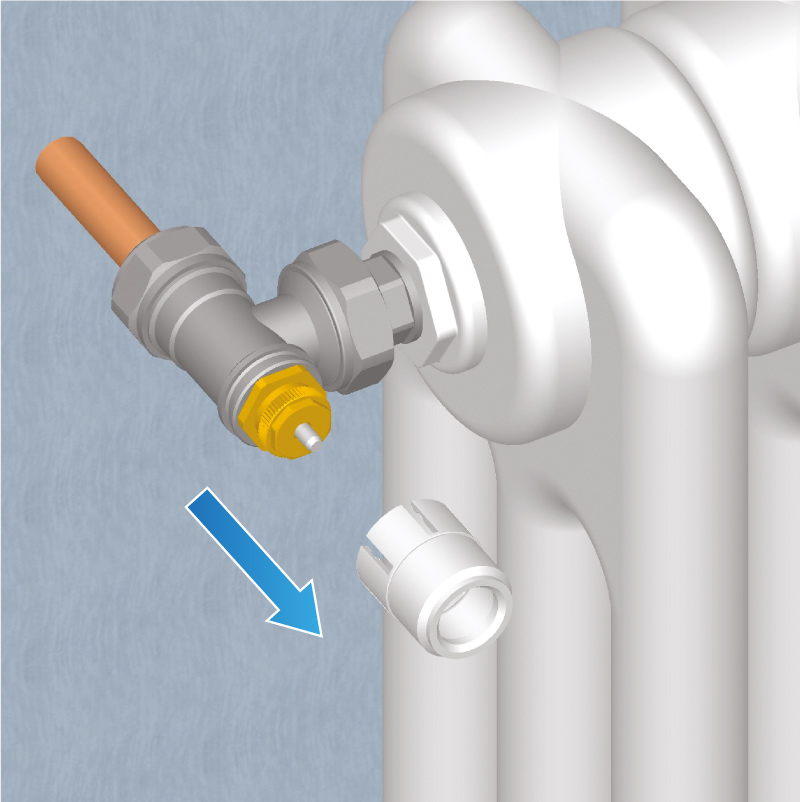
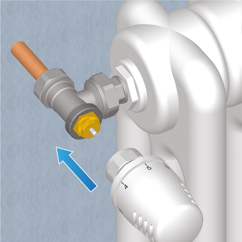
Application of valves and thermostatic heads for radiators
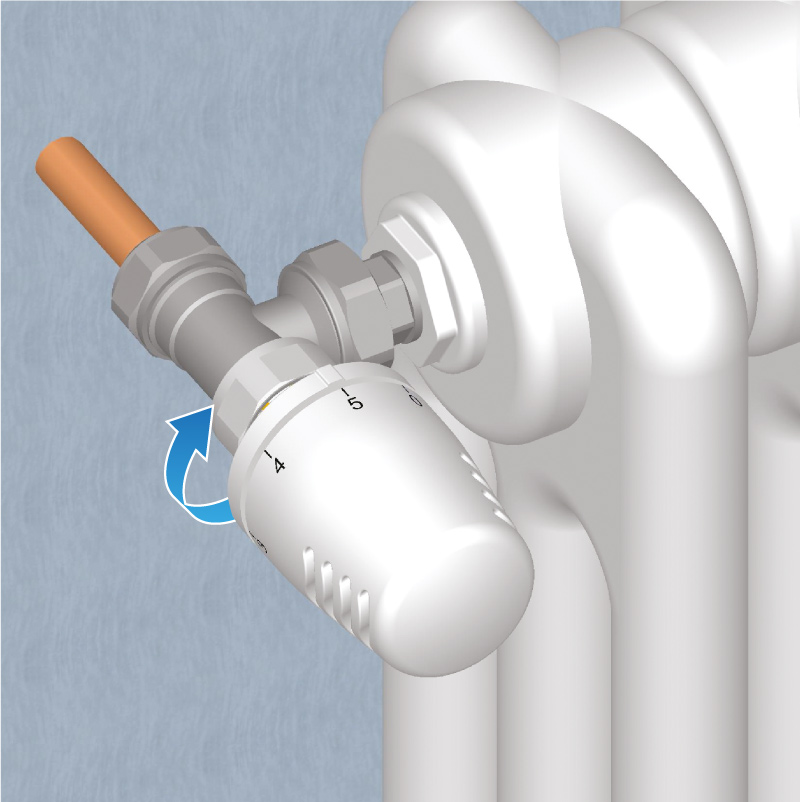
The application of thermostatic heads on ICMA thermostatic valves is the best independent, simple and low-cost solution to automatically adjust the temperature, only where and when needed.
ICMA thermostatic heads allow the temperature in the environment in which they are installed to be constant.
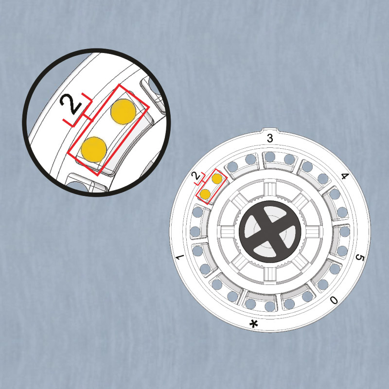
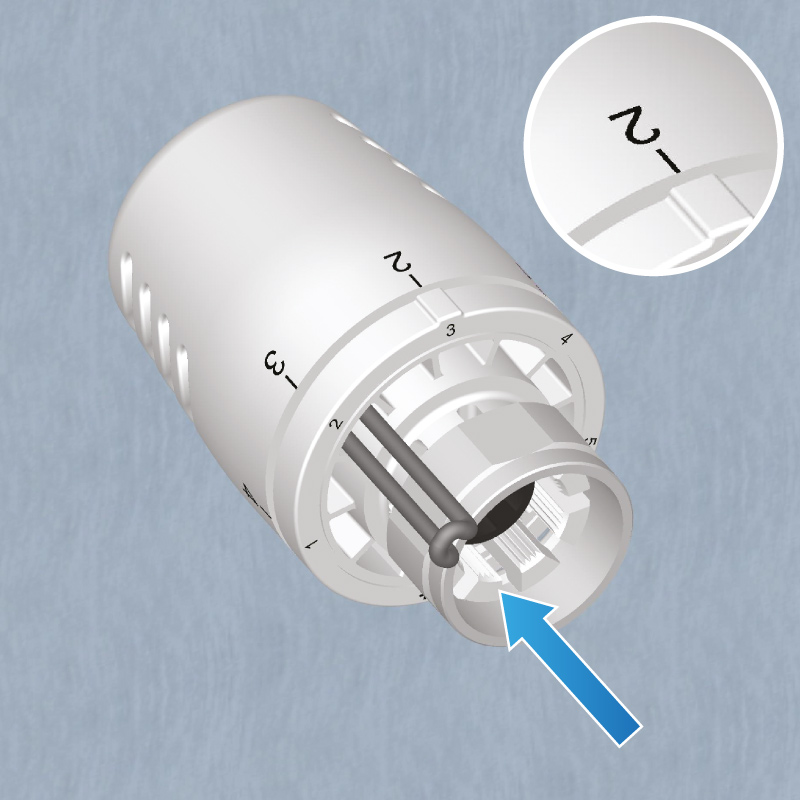
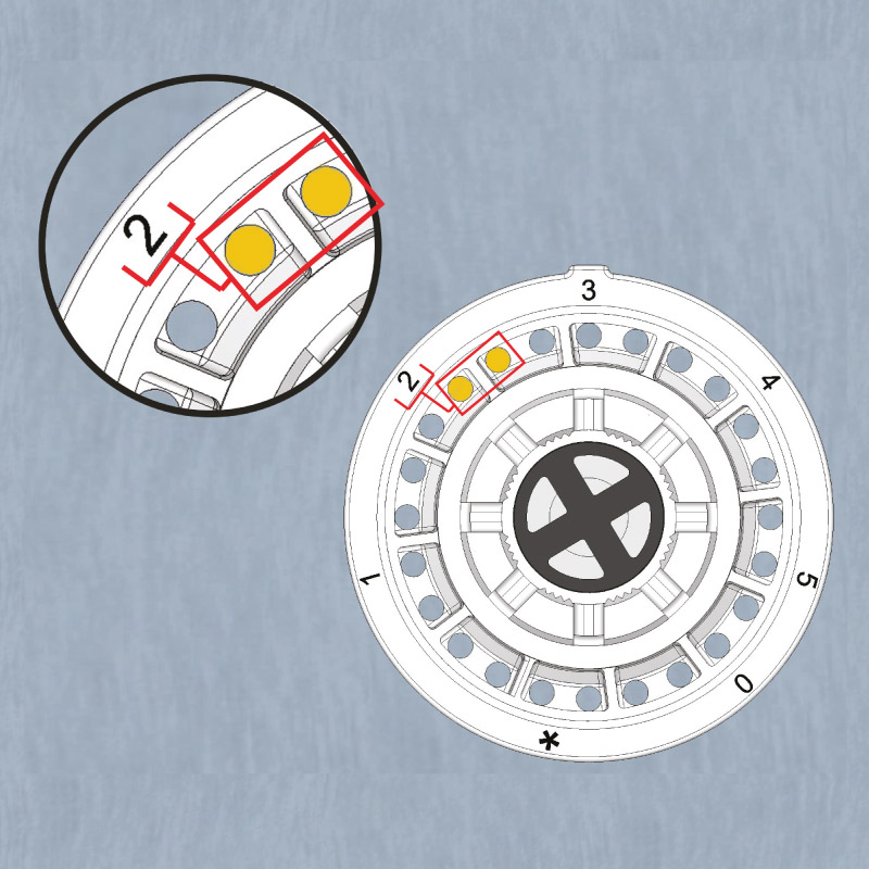
The numbers on the handle represent the set temperature.
Temperature regulated in °C

Position of the thermostatic head
ICMA thermostatic heads do not require electricity; they are equipped with a liquid sensor with low thermal inertia and a coupling system to the valve body M28x1.5 (art. 1100) and M30x1.5 (art. 1101).